Honeywell 2-Port Valve⁚ Wiring Basics
This guide provides fundamental wiring instructions for Honeywell 2-port valves. Understanding wire colors and functions is crucial for proper installation. Correctly identifying live, neutral, and earth wires ensures safe and effective operation. Always consult the specific valve’s documentation for detailed diagrams and safety precautions. Incorrect wiring can lead to malfunction or damage.
Understanding the Wires
A Honeywell 2-port valve typically utilizes several wires for power and control signals. These wires connect the valve to a power source (live and neutral) and a control system (e.g., a thermostat or programmer). The specific wire configuration may vary depending on the valve model and the type of system it’s integrated into. Common wires include a live wire (often brown), supplying power to the valve’s motor; a neutral wire (usually blue), completing the electrical circuit; and an earth wire (typically green/yellow), providing grounding for safety. Additional wires might be present, such as those for end switches or other control functions. These switches signal the valve’s position (open or closed) to the control system. Understanding each wire’s purpose is essential for correct connection and system functionality. Incorrect wiring can lead to malfunction or damage; always refer to the manufacturer’s instructions for your specific valve model.
Common Wire Colors and Functions
While specific wire colors can vary slightly depending on regional electrical codes and the manufacturer’s choices, certain conventions are generally followed. The live wire, supplying power to the valve’s motor, is frequently brown. This wire carries the main electrical current required for valve operation. The neutral wire, completing the electrical circuit, is commonly blue. It provides the return path for the current. The earth wire, crucial for safety, is usually green/yellow. It provides a path for fault currents to ground, preventing electrical shocks. Grey and orange wires are often used for the valve’s internal end switches, signaling the valve’s open or closed position to the control system. These switches are essential for feedback to the controlling device. Remember that these are common conventions; always verify the specific wire colors and their functions using the wiring diagram provided with your Honeywell 2-port valve. Never assume wire functions based on color alone – consult the manufacturer’s documentation.
Identifying Live, Neutral, and Earth
Before connecting your Honeywell 2-port valve, accurately identifying the live, neutral, and earth wires is paramount for safety and correct functionality. Use a voltage tester to confirm the presence of voltage on each wire. The live wire will show a voltage reading relative to the earth. The neutral wire will show little to no voltage relative to earth and the live wire. The earth wire should not show any voltage against either the live or neutral. Incorrect identification can lead to electrical shocks or damage to the valve. If you are uncertain about identifying these wires, consult a qualified electrician. Never attempt electrical work if you are unfamiliar with the proper safety procedures. Always switch off the power supply to the valve before undertaking any wiring work. Double-check your work before restoring power to the valve to avoid potentially dangerous situations. Take necessary precautions to ensure your safety and the proper functioning of the valve.

Wiring Diagrams for Common Configurations
This section details wiring diagrams for common Honeywell 2-port valve setups, including S-Plan and Y-Plan systems; Understanding these diagrams is crucial for correct installation. Refer to specific diagrams for your system configuration. Incorrect wiring can cause malfunctions.
S-Plan System Wiring
The S-Plan system uses a single 2-port valve to control both heating and hot water. Wiring typically involves connecting the valve’s terminals to a programmer or thermostat. The live wire (brown) provides power to the valve motor. The neutral wire (blue) completes the circuit. The earth wire (green/yellow) ensures safety by grounding the valve. Two additional wires (grey and orange) connect to the valve’s end switch, signaling its open or closed state. The programmer controls the power to the valve, determining whether heating or hot water is active. Always ensure proper insulation and secure connections. Incorrect wiring can lead to system malfunction, potentially causing damage or safety hazards. Consult the Honeywell 2-port valve’s specific wiring diagram for your model. Before commencing any wiring work, always isolate the power supply to prevent electric shock. Carefully check all connections before restoring power to the system. Remember to refer to the manufacturer’s instructions for your specific valve model and system configuration for detailed wiring information. Always prioritize safety when working with electrical systems.
Y-Plan System Wiring
A Y-Plan system uses separate valves for heating and hot water, offering independent control. Wiring a Honeywell 2-port valve in a Y-Plan setup requires connecting to a different control system compared to an S-Plan. The live (brown), neutral (blue), and earth (green/yellow) wires connect as standard. However, the control signals to the valve will originate from separate zones within the Y-Plan system, often through a central programmer or individual thermostats. The grey and orange wires, connected to the valve’s internal switch, provide feedback to the control system. This feedback indicates the valve’s position—open or closed. Incorrect wiring can cause heating or hot water malfunctions. Always consult the specific wiring diagram for your valve model and control system before starting. Prioritize safety by isolating the power supply before any wiring work. Double-check all connections to prevent electrical hazards. Mismatched wires can result in system failure or damage. Refer to the manufacturer’s instructions for detailed guidance and troubleshooting tips if issues arise during the installation process. Ensure all connections are secure and well-insulated to prevent short circuits.
Wiring with a Junction Box
Utilizing a junction box simplifies wiring for Honeywell 2-port valves, especially in complex setups. The junction box acts as a central connection point, consolidating wires from various sources, such as the programmer, thermostat, and power supply. This organized approach minimizes wiring clutter and improves safety. Before commencing, always switch off the power supply to prevent electrical shocks. Carefully refer to the specific wiring diagram provided with your junction box and valve model. Each wire—live, neutral, earth, and control signals—must be connected to the correct terminals within the junction box. Incorrect connections can lead to system malfunction or damage. Properly label all wires to ensure future maintenance ease. Use appropriate wire strippers and connectors for secure and safe connections. Ensure that all connections are tight to prevent loose wires causing shorts. After completing the wiring, carefully inspect each connection to identify and rectify any potential issues. Thorough inspection minimizes the risk of malfunctions, ensuring optimal system performance. Consult a qualified electrician if you are unsure about any aspect of the wiring process.

Troubleshooting Common Wiring Issues
This section addresses common problems encountered during Honeywell 2-port valve wiring. Troubleshooting steps include checking for power, verifying valve operation, and inspecting connections for loose wires or shorts. Consult the manual for further assistance.
No Power to the Valve
If your Honeywell 2-port valve isn’t functioning, the first thing to check is whether it’s receiving power. Begin by verifying the power supply to the circuit. Use a multimeter to test for voltage at the valve’s terminals. Ensure the power switch controlling the valve is turned on. Inspect the wiring for any breaks, loose connections, or damaged insulation. Check the fuse or circuit breaker protecting the circuit. A blown fuse or tripped breaker indicates a potential fault in the electrical system that must be addressed before proceeding. If the power supply and wiring appear to be intact, the issue may lie within the valve itself or another component in the system, such as a faulty programmer or thermostat. Refer to the troubleshooting section of your valve’s instruction manual for more detailed guidance. If the problem persists after these checks, consider seeking professional assistance from a qualified electrician or HVAC technician.
Valve Not Opening or Closing
If your Honeywell 2-port valve fails to open or close, several factors could be at play. First, verify the valve is receiving the correct electrical signal. Use a multimeter to check for continuity and voltage at the valve terminals. A faulty actuator motor could prevent movement; inspect the motor for any signs of damage or binding. The valve’s internal components might be obstructed, causing it to jam. Check for any debris or mineral buildup that could be hindering its operation. Examine the valve’s manual override mechanism, if present, to see if the valve can be moved manually. If it’s stiff or unresponsive, there might be an internal mechanical problem. The issue might stem from a problem with the control system, such as a malfunctioning thermostat or programmer. Ensure the control system is sending the correct signals to the valve. If the valve is still malfunctioning after these checks, it might require professional repair or replacement. Consult the manufacturer’s instructions or a qualified technician.
Incorrect Valve Operation
Experiencing erratic or inconsistent operation from your Honeywell 2-port valve? Several factors could be responsible. Firstly, ensure the valve is correctly wired. Double-check all connections to eliminate loose wires or incorrect terminal assignments. A faulty wiring diagram or mismatched components could cause incorrect behavior. Examine the valve’s power supply; inconsistent voltage can lead to intermittent operation or failure to reach the desired state. A malfunctioning control system can also be the culprit. A faulty thermostat, programmer, or other control unit might be sending incorrect signals to the valve. Furthermore, check for any obstructions within the valve’s flow path. Debris or mineral buildup can interfere with smooth operation. If the valve is a motorized type, a weak or damaged actuator motor might be responsible for erratic performance. Finally, consider the possibility of a defective valve. If all other components are functioning correctly, the valve itself might require replacement. Always refer to the manufacturer’s instructions or seek professional assistance for troubleshooting.
Advanced Wiring Scenarios
This section explores complex setups, such as integrating smart home systems, using multiple valves, and advanced control systems. Consult specialized documentation for detailed guidance on these more intricate configurations. Safety precautions remain paramount throughout the process.
Integrating with Smart Home Systems
Integrating your Honeywell 2-port valve into a smart home system offers advanced control and automation possibilities. Many systems utilize relays or controllers to interface with the valve’s wiring. These intermediary devices translate the smart home system’s commands into the appropriate electrical signals required by the valve. It’s crucial to select a compatible relay or controller that matches the valve’s voltage and current requirements. Improper voltage or current can damage the valve or the smart home system. Before connecting any smart home devices, ensure the valve is correctly wired according to the manufacturer’s instructions. Consult the documentation for both your smart home system and the Honeywell valve for compatibility information and detailed wiring diagrams. Failure to follow these instructions may result in system malfunction or safety hazards. Always prioritize safety by double-checking all connections before activating the system. Consider professional installation if you’re unsure about any aspect of the integration process.
Using Multiple Valves in a System
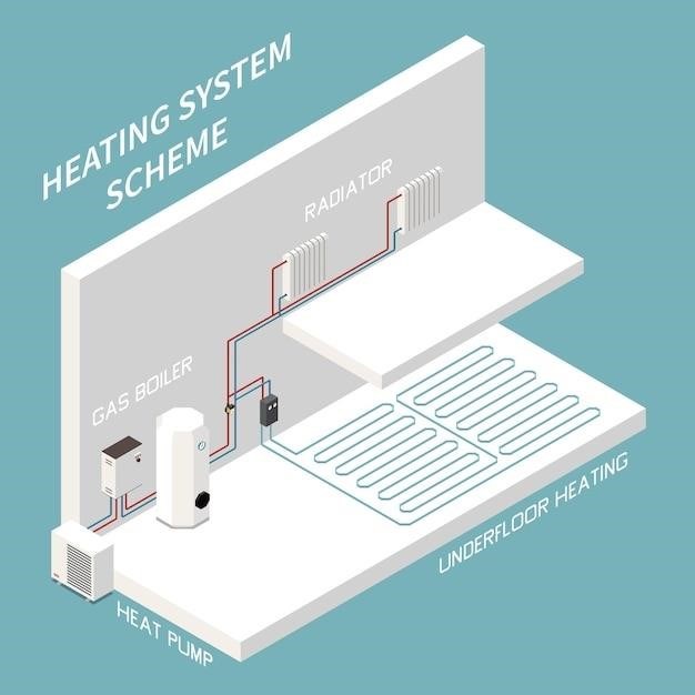
Employing multiple Honeywell 2-port valves within a central heating system necessitates careful planning and wiring. Each valve requires its own power supply and control circuit, preventing interference between individual zones. A central control unit, such as a programmer or thermostat, manages the operation of all valves. Wiring diagrams will vary depending on the system’s complexity and configuration. Common configurations include using a junction box to consolidate wiring for multiple valves. Always ensure correct polarity for each valve to avoid damage or malfunction. Consult the manufacturer’s documentation for guidance on wiring multiple valves. Consider using appropriately sized wiring to accommodate the increased current draw. Improper wiring can lead to inefficient operation, system instability, and potential safety issues. Professional installation is advisable for complex systems involving many valves to ensure optimal performance and safety.
Advanced Control Systems
Integrating Honeywell 2-port valves with sophisticated control systems offers enhanced precision and efficiency in managing heating zones. These systems often incorporate features like smart thermostats, weather compensation, and remote monitoring capabilities. Wiring configurations for such advanced systems become more complex, often involving communication protocols like BACnet or Modbus. These protocols allow for seamless integration with building management systems (BMS) for centralized control. Specialized wiring harnesses and interfaces may be necessary to connect the valves to the advanced control system. Programming expertise may be required to configure the system’s parameters and ensure proper operation of the valves. Proper grounding and shielding of communication lines are crucial to prevent signal interference and data corruption. Always refer to both the valve’s and the control system’s manuals for specific wiring instructions and compatibility information. Professional installation is highly recommended for advanced control systems to avoid potential issues and ensure optimal performance.


